SIMPLIFIED DESIGNING with AutoDesign:
Using the AutoDesign feature, entering minimum design requirements results in a complete transformer design realization . The optional Core Library of over 600 cores and the optional Conductor Library must be authorized for the AutoDesign feature to function.
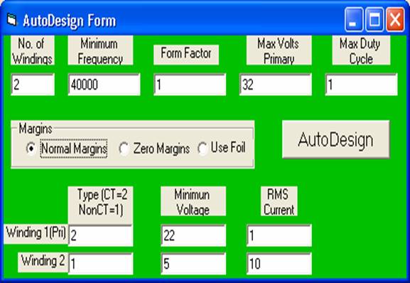
Enter only the following data:
Enter the number of windings (2 to 8)
Enter the minimum operating frequency in Hertz
Enter the form factor (1.11 for a sine wave, 1 for a square wave, etc.)
Enter the maximum expected primary RMS voltage
Enter
the duty cycle in per unit (Usually 1, but less for pulse width
The
program uses the margins stored with the conductors unless the “Use Foil” or
“Zero Margins” radio button is selected.
If “Use Foil” is
selected, the program calculates foil parameters to fit the core.
Enter the winding type for each of the windings (2 for center-tapped,
Enter minimum RMS voltages for each winding
Enter RMS currents for each winding.
It is not necessary to enter
Click on AutoDesign. (If “No Dongle Installed”
error occurs, see “Installing the Security Device” below.)
The
program completely designs the transformer and, when finished, displays the output results.
The rest of the forms can be displayed by clicking on VIEW then VIEW ALL
FORMS:
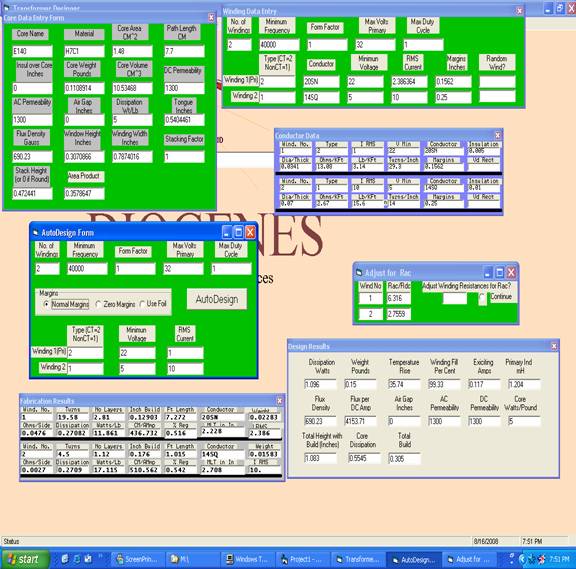
The “AutoDesign” form can be added to the display from the bottom minimized bar. The Core Data Entry form and the Winding Data Entry form with green backgrounds are input forms which, in AutoDesign mode, are filled out by the program. The Design Results form and the Fabrication Results form with grey backgrounds are output forms. The “Design Results” form contains information which the designer can use to determine if the design is optimum. The “Fabrication Results” form contains information the shop can use in the production process.
The Conductor Data form includes the data parameters for each conductor from the Conductor Library. The blue background denotes an input form, but it is completed by the program, with or without the AutoDesign feature.
If this project is saved now, all the input forms and data are saved. When re-opened, “Calculate” from the main menu will reconstitute the output data.
Calculations in AutoDesign mode use the maximum temperature rise of 50 degrees centigrade by default. A different temperature rise can be entered under “Options” on the main menu.
Initially, calculations are made without regard to the increase in resistance due to operating frequency. The “Adjust for Rac” form shows the estimated ratio of AC resistance to DC resistance because of skin depth and proximity effects for each winding.. If it is desirable to recalculate the transformer using the higher AC resistances, answer “Yes” and select “Continue”. Subsequent calculations will include the AC resistance values. If the AC resistance presents a problem, a recalculation using foil conductor is usually quite effective in reducing the ratio of Rac to Rdc.
Possibly you are not entirely satisfied with the design. Maybe you don’t have an E140 core with H7C1 material on the shelf. Or your shop’s winding practices can’t meet the winding fill requirement (this calculation includes a 5% bulge factor). You can modify anything in the input forms and recalculate manually. Manual design is very flexible, allowing use of any core and any conductor. The Cores Library and Conductor Library can alleviate most of the dog work of entering data.
The output data can be selectively printed in two collections. :
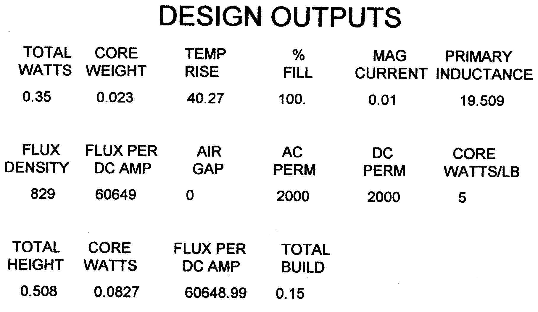
The Design Outputs printout contains data useful to the designer to determine if the design requirements have been adequately met. This is the same data as in the Design Results form.
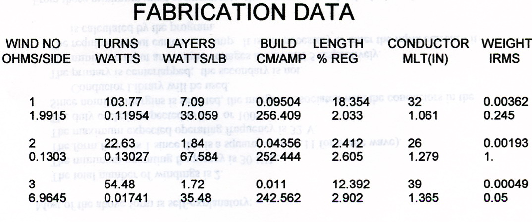
The Fabrication Data printout shows data needed by the shop to fabricate the transformer. This is the same data as is available in the Fabrication Results form.
The design can now be:
1. Sent to the shop for fabrication.
2. Saved for future reference.
3. Modified and recalculated using the manual design
techniques described in the online manual.
4. Printed. In addition to the above described
printouts, any of the design forms can be printed.