Transformer
Designer
V4.0
with
AutoInductor
Simplified designing with
![]()
AutoInductor
Using the AutoInductor feature, entering minimum design requirements results in a complete DC biased inductor design realization . The optional Core Library of over 600 cores and the optional Conductor Library must be authorized for the AutoInductor feature to function.
Start Transformer Designer:

Click on Agree to open the Main Transformer Designer Screen:

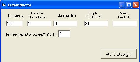
Clicking File then AutoInductor will open the next screen:
:
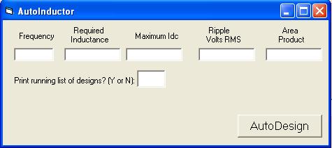
This design form is the only form required to be completed
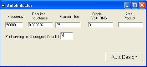
This form has been completed to design a 26 microHenry inductor with 25 Amps of DC and 3 Volts RMS ripple at 50 KHz. If you have and idea of what Area Product is required, it can be entered. Otherwise, leave it blank and the program will make a guess. A “Y” or “Yes” can be entered in the text box for “Print running list of designs" for later comparison of designs.
Click on AutoDesign and the program calculates an inductor using the chosen Area Product to select the core.
![]()
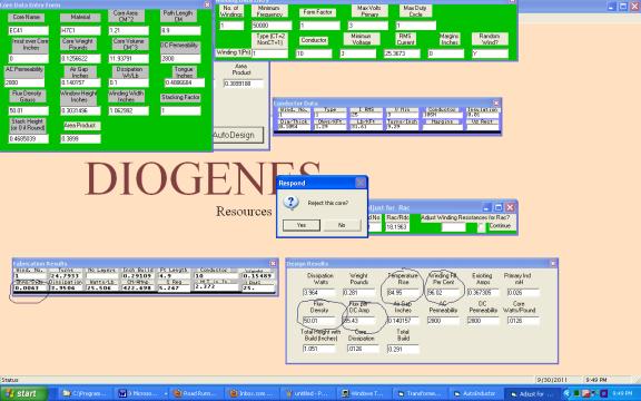
You now can review the outputs to determine if this inductor design meets your requirements. The usual requirements which will cause rejection of a design include % winding fill, temperature rise, total core flux, and series DC resistance.
The two gray forms at the bottom of the screen contain the output information.. The rest of the forms are input forms which were filled in by the program for this automatic design.
The 96% winding fill is probably ok. There is a bulge factor in the calculation which exaggerates the fill somewhat.. Different shops have different practices which should be considered.
The 85 degree C temperature rise is probably too high for most applications. Insulation systems are readily available which can withstand this temperature (40 degrees ambient plus 85 degrees = 125 degrees C). I would rather see a rise closer to 50 degrees C. UL (last I heard) requires a surface temperature rise of less than 40 degrees C to avoid an expensive series of tests required to gain approval.
The 85.43 Flux/DC Amp times the 25 DC Amps = 2136 gauss + the 50.01 AC gauss = 2186 Gauss total. This is not excessive, since the H7C1 ferrite material saturates above 3000 gauss.
The .0063 Ohms/Side times the 25 ADC = 0.158 Voltage drop. This is probably not excessive unless the output voltage is very low.
Since this design is not acceptable due to excessive temperature, I will reject it by answering Yes in the Respond Question Box. This causes another design on a larger core.
![]()
![]()
![]()
![]()
![]()

![]() The problem with this design is excessive total flux density.
The DC flux density is 248 times 25 or about 6200 Gauss with a material
(ferrite) which saturates at a little over 3000 Gauss.
Therefore, another rejection is warranted.
The problem with this design is excessive total flux density.
The DC flux density is 248 times 25 or about 6200 Gauss with a material
(ferrite) which saturates at a little over 3000 Gauss.
Therefore, another rejection is warranted.
We can continue with these rejections and obtain as many designs as we need until satisfied with the design. Note that the inductors get heavier with almost every new design because of the increasing area products.
After a string of designs (about 13), choose No to not reject the core. This will end the design series and, since we chose to print the series, it will automatically print.
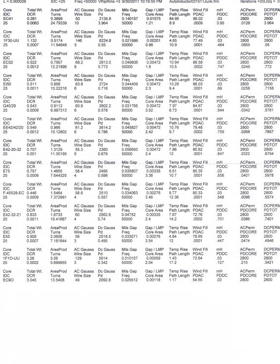
Note that the 3rd design, with the EC52 core, the temperature rise is low and the flux density is within the 3000 Gauss limit. Also, the DC resistance is low. This core looks acceptable.
However, the 4th design, on the EI50 core, is lower in weight and is superior in some other parameters, notably flux density and temperature rise. This is no doubt due to a different core shape, since the Area Products would signify the EC52 core is superior. The subsequent cores grow progressively heavier.
For a calculation at low frequency, consider:
The first calculation yields:

This design has problems with temperature rise (321 degrees C), total flux density (21575 gauss, since saturation will occur at approximately 15,000 Gauss for this M6X silicon steel core), and probably series DC resistance (10.2 Ohms times 10 ADC causes a DC voltage drop of 102 volts). After a series of calculations we arrive at:
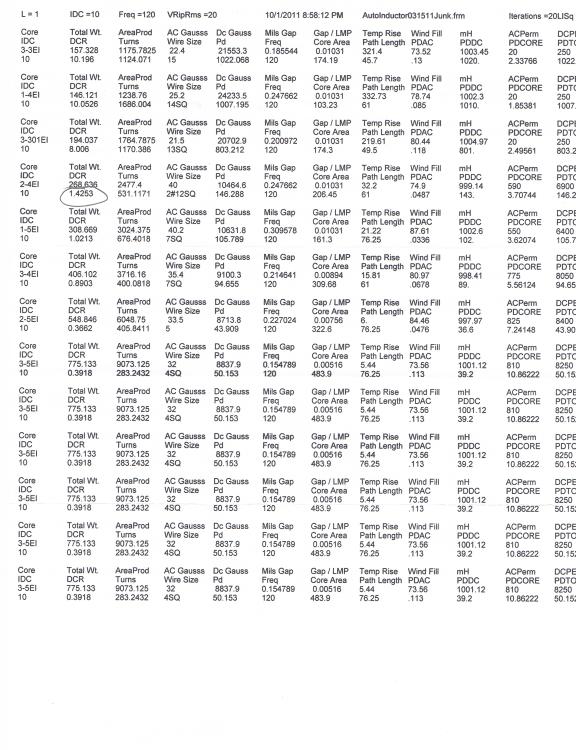
Perusal of this data indicates that the first feasible design is on the 2-4EI core (which is a double stack of 4EI laminations). The temperature rise and the flux density are within bounds. The one salient problem is the series DC resistance (1.425 Ohms times the 10 ADC equals 14.25 DCV drop). If this is important, it is lower in some of the subsequent designs but at a penalty of dramatic increase in weight (and, therefore, cost).
Another possibility would be to use foil conductor in place of wire. If the number of turns remains the same, substitution of conductors should affect only the winding fill and the winding resistance.
Start AutoInductor, input the parameters for the design. In the Area Product text box, enter a value slightly less than that shown in the printout (about 2470). This should calculate the following:

Click on “No” in the Respond form.
In the Winding Input form (the green one on the right above) remove the 2#12SQ and enter .005x5.75 as a guess at the size of the foil required. The 5.75 comes from the 6 inch window width from the Core Input form (the green form on the left above) but leaving some margin at each side of the coil.
Click on another text box and an action form appears, with several options. Choose ”Calculate Foil Parameters”. The Conductor Library opens with the chosen conductor at the bottom, which will have all its parameters specified. Select this item by clicking at the left of it, and click on “Select” at the bottom and all the parameters will be loaded into the input forms. Click on "Calculate", then "Show All Forms" to display the following:

Since the Winding Fill is excessive, try a smaller foil (.004x5.75) and recalculate. This is found to cause excessive Winding Fill also, but when .003x5.75 is used the fill is ok:

Note that the resistance has been reduced to about half, but the weight has increased by about 20 pounds. About the same affect on resistance could be achieved by using a 3-4EI core, but with a 137 pound weight penalty.
It is assumed that, with the many design possibilities available, the designer will be able to choose one that is best for his unique requirements.